The Build Team

The Build Team
Me and My Master Mechanic Sean

April 9, 2008 The Godfather Project Begins (Codenamed: Project X)

Welcome to the custom chopper build blog for the 2008 SMW Godfather Pro Street. The purpose of this blog is to document in detail the process of building my custom show chopper.


About the bike:
2008 softail frame/300mm tire (5" backbone stretch, -2" stretch downtube 46 deg. rake)
100" Ultima Motor

  • 1600cc
  • Bore: 3.875"
  • Stroke: 4.25"
  • Piston: Forged
  • Compression: 9.6:1
  • Rated Power: 110RW HP - 110 LB FT Torque

S&S Super G Carburetor with S&S High Flow Air Filter & Adapter Kit
Accessories Unlimited 6 Speed RSD Transmission
Martin Bro's Daisy Cutter Pipes (RSD)
Krafttech 4" Stretched Gas Tank
2" Chrome Front Forks
Tribal 6 Degree Raked Trees
Chrome 7 1/2" Stretched Bullet Headlight
21x3.25 Billet Lawless Front Rim
120MH21 Avon Tire (front)
18x10.5 Billet Lawless Rear Rim
Avon Venom 300 Series Tire
13" Softail Fender
Chrome 2" Adjustable Shocks
SMW Winged Oil Tank
Accutronix Tribal Chrome Forward Controls
+3" Chrome Shifter Rod
Dakota Digital Speedometer

Performance Machine Contour Hand Controls

Russell Pro System Oil Lines (compression lock)

Machined Oil Pressure Gauge


I purchased most of the parts from a company called Southern Motorcycle Works in Ardmore, OK. The total cost of parts and shipping was $17,739. The shipping was done via FedEx Freight on 2 pallets. One weighing 300lbs (class 85), and the second weighing in at 450lbs (class 250). The total delivery time was 4 days from door to door.

About the Builders:
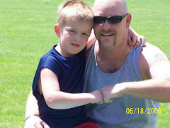
As you can see there are only two builders for this project, myself and my son Sean who is 8 years old. My experience building a motorcycle is next to none, but Sean assures me that his experience is all we need.


The Bench & Tools:

Given the option to buy a standard motorcycle stand

for about $500 + shipping, I decided to go the more economical route and build a bench that

would suit

my needs. I probably have $60 in the bench and that includes the mat covering. This means I can use it as a heavy duty garage bench or in the future for tire replacements and the like. Homemade bench or beer……hmmm not a tough decision.

Since every “builder” needs a tool box and his own tools, Sean

was given my old toolbox and I had to buy a new one. Just one of those rights of passage as a young man I believe.

So off to the Sears I go, and let’s just say that a bigger toolbox

means I need more tools to fill the drawers. We pretty much have everything we need for this project (standard hand tools, Air Compressor, Impact Gun, Air Ratchet, Die Grinders, etc.) Now all we have to do is RTFM.

I will continue to update this blog as often as possible, and hope to include lots and lots of

pictures along the way. Stay tuned more to come…….

April 10, 2008 Day 1 (Parts Arrival)


Today is the big day when the parts are to arrive from SMW Inc. I placed a call to the FedEx freight yard to let them know I could take the order as soon as 5:00AM. Of course the goods did not show up until 4:00PM.

All of the parts arrived on two pallets, and the packaging was incredible. Everything was secure and fit nicely in the boxes.

The unpacking started with the help of the rest of the family, except Sean since he was not arriving at the house until the next day (Friday). We had everything out of the boxes and on the shelves in a few hours. Then the celebratory tequila shots began as we all marveled at the massive amounts of parts and pieces.


April 11, 2008 Day 2 (Assembly) The Learning Process Begins

Day two started as you can imagine with a pretty severe hangover, but being the veteran that I am, I mustered the energy to load the assembly DVD that came with my parts. The video was created by a company called 2Wheel Films, and depicts a guy building a 2005 pro street chopper. So as I watch the first chapter, this explains how to mount the swingarm to the frame.

Not wanting to get to far ahead of myself I decide to go down and follow the instructions. To my amazement the swing arm had 2 bearings sliding around the swing arm shaft. Now this seemed very strange since mister assembly on the DVD did not have these? With some investigation I find that these bearings need to be pressed into the swing arm. Hmmmm……now this poses a bit of a problem right off the bat since neither me nor anyone I know owns or has access to a bearing press.

Being the resourceful person that I am, I try several methods to get the bearings seated, including a few creative methods that included large sockets and a sledge hammer. After several attempts I could not get the bearing to start straight, and decided I should cut my losses and let someone with the right equipment tackle this job.

The first place I called was a local tire store, and Kyle assured me they could do it. With swing arm in hand and the dog (Boss) loaded into the truck I headed off to see Kyle. I should have suspected a problem when Kyle got the manager and the both were doing a lot of head scratching, and saying “hmmmmm”. Manager Tom said “We will probably have better luck if we hear the swing arm and drop the bearing in. GENIUS!! Why didn’t I think of that? Maybe it was the Tequila? Tom says about an hour and between $50 and $100. Given the alternative (sockets and hammers) I agree and head off to get a sandwich.

Fifteen minutes later I get a call from Tom, I am thinking man that was fast! But to my surprise Tom had other news. He said that they had heated up the swing arm and the bearing dropped right in, but when they went to cool it, the plastic insert inside the bearing had melted and poured out of the bearing. I said I would be right there…….

The local bearing shop did not have what I needed so off to the Harley Dealer (HD) I go. Dave at the parts counter looks up a Harley swing arm bearing and warns me “these babies are spendy”. Just what you want to hear right? So he brings out the bearing and of course the inner diameter is larger that mine. So he looks up the only other swing arm bearing the HD uses and of course…. they are out of stock. So Dave explains they are $60 a piece and it will take 7 – 10 days to get them. This is not starting out so well.

My next stop is the HD service department to find out if the pro’s can do this job. The very slow moving service tech assures me they can do the job for about $125.00. Now there are several benefits here, primarily if the hose up the bearings they have access to more that I do not have to pay for.

Not a single part installed and I am already $250 bucks poorer. The hangover hurts more now then ever. The bearings are due to arrive at the HD dealer next Friday 4/18. More to come on this saga later.

After I got back home I decided to take a look at the next steps on the DVD. This was putting on the rear tire which requires the swing arm to be mounted, so I did the next best thing and used some large tie wraps to secure the swing arm in place. This will also make removal easy when I have to head back to HD. With the rear tire mounted on the rear axle I was able to move on to the next step.


By this time it is late afternoon and I have managed to tie wrap a swing arm and burn up a $60 bearing. Let’s hope Mr. Assembly (MA) as I will call him has a bit easier task next?

I fire up ye ole DVD once again, and we are going to assemble the neck bearings and triple trees. I watch the chapter and with great hope head down to the assembly area. I unbox the chrome forks and they look just like the ones MA used. I get the remaining parts unboxed and then realize that on MA’s frame the neck cups and bearing races are already installed on his frame. Ok here we go again. I play with the parts like a kid with Rubics Cube for the first time. Twisting, turning and mimicking trying to fit together a 2500 piece puzzle. Finally I get the cups and races installed and feel a sense of completion.

Next are the triple trees and steering neck. No surprise here, MA’s triple trees install from the bottom up, and mine are the exact opposite (top down). No biggie, a little bit of common sense and they were on.


I try to slide the forks into the triple trees and determine that the large nut on the top that MA used to secure the fork to the triple tree does not fit into the top of my tree!! You must be kidding…….


After looking at the parts included with the triple trees I notice these two threaded chrome caps. I stuck those caps in every hole there was (insert your own bad joke here) before I realized that you had to remove the shock tube adapters and insert these flat top caps. Now if you have ever tried to hold a round object with one hand and an open end wrench in the other hand, you know that you are limited at best. I finally decided to clamp the fork in the triple tree about half way so I could get enough torque to loosen the adapters. This worked great, except for the spring shooting out the top of the fork at mach ten. Springs reloaded, caps installed and forks FINNALY in the trees.

Now I can move on to installing the front tire. This seems pretty straight forward, remove axle and spacers and install tire, axle, and spacers. With a little help from a small car jack I able to get the holes lined up and the axle started. The axle slides in almost all the way before I make the expert determination that the chrome plating is keeping us from inserting the axle all the way. So off to the wire wheel I go. A little effort and the chrome plating peels right off the axle end. She slides in like butter.

I begin to sit back and marvel at my work and open the first beer of the day. Not so tasty, but with every chug my head hurts less and less. I decide this is a good stopping place for the day, and start looking at some parts I can install the next day. It is during this process I notice the label on the front brake caliper that says “left hand brake caliper”. Oh crap!!!! I installed the wheel with the brake disc on the right side. I also noticed that I installed the shocks on the wrong sides. This is purely aesthetics, as the right shock has a small gap in the chrome to place a pry bar. This gap is visible if they are reversed. Looks like my work all has to come apart in the morning.

I am learning the DVD is a better beer coaster than training aid. Another day done and a few more lessons learned.

April 12, 2008 Day 3 (The Master Mechanic Arrives) & We Make Progress

Day three started with the disassembly of the previous days work. After removal of the front tire and swapping the forks I was back to square one.

My son Sean (also my master mechanic) arrived and immediately began assessing the situation. I solicited his help to assemble the Ultima forward hand controls onto the drag style handle bars. Box open, parts unpackaged, and no directions, just a wiring diagram. Par for the course at this stage of the game.

I decide that we need to drill 4 holes into the bars to hide the wiring for the turn signals, push button start, high and low beams, and the horn. The whole idea is to hide all of this stuff as much as possible. Maybe next time I will up the ante and install internal throttle cables and an internal twist clutch?

Sean assisted me in drilling the holes by holding the bars on the bench. As you can imagine he has a million questions, but then again so do I.

We did ruin our safety record of 3 days today since Sean did not know about using your hand to brush metal shavings into the garbage. I removed the shavings from his hand, and another valuable lesson was learned.


With the bars 90% assembled Sean was able to mount them to the handle bar risers. We also slipped the seat pan in place to get a general idea of how it would sit. Important to note here that I order a seat pan and not a complete seat so I could have it upholstered to my specs. Maybe shark or stingray skin? We will see. I may post a vote and include human skin for a real unique touch.......


Next Sean and I installed the 7-1/2” stretched bullet headlight. I will be important to get all of the wires together to run through the final wire loom.


Next came the engine and transmittion installation. I asked my friend and Brittani’s dad Cary to give me a hand getting the heart of the beast installed. Although he was hungover he agreed to give me a hand and we had both the engine and tranny set in the frame in short order. None of the components are bolted in yet, since we have to get the swing arm completely installed before we bolt the drive train down. To top off the days progress we set the KraftTech 4-1/2” stretched gas tank on the backbone.

Time was running short since we were having company over to celebrate the first 70 degree day of the year. Off to Boston tomorrow for a week, but the project will continue when I get home on Friday 4/18.

April 17, 2008 Day 4 (Baked Swing Arm Anyone…….Anyone?)

Today was the big day that HD called and said that my swing arm bearings had arrived. After talking with my friend Marshall via telephone, we agreed that with a “proper” bearing press tool and some heat/cold applied on the appropriate parts and I should be able to save myself the $100 + bucks the pro’s wanted to get the things installed. So I eagerly arrive home from the HD dealer and promptly package my bearings in a zip lock bag and into the freezer they go.

Next was the heat….Hmmmm how about using the oven? Perfect! Out come the oven racks and in goes the swing arm, sort of. It never dawned on me that the swing arm might not fit in the oven. So, I did the next best thing and turned on the broiler. I waited as long as humanly possible for an impatient man, and then started to press using the new fangled press I bought. After 12 attempts and some very hot tools, I was in the same spot as before, I could not get the bearing started straight. Now this is becoming a bone of contention with me and it’s time to get serious. Out comes the die grinder fitted with a sanding drum. I made about 6 light passes on the swing arm and wallah! The darn bearing dropped half way in!! With some help from a large mallet the first bearing was seated. I repeated the process and I was done within 10 minutes. Lesson learned here…..do it yourself and get it done right.

April 18, 2008 Day 5 (The Driveline Comes Together)

Today Sean and I started on bringing the driveline together. We started by installing stator and the 32 amp charging system, including the voltage regulator and inner primary which connects the engine and transmission together.
Sean started by assembling the engine side drive belt gear, while I started to line up the tranny and engine. At this point things are going pretty well, and if you are wondering what happened to Mr. Assembly? Well,
after having to beat the swing arm bearings in, and other documented issues, he has been demoted to 3rd string for information. I was able to get the engine and transmission lined up and the inner primary installed with no issues. This is a good time to mention that the left rear engine bolt cannot be tightened while the inner primary is installed, so you must get everything lined up, the remove the primary, and then tighten everything up. In my case it took me several attempts before I was happy that there was no binding when the primary was finally installed.

April 19, 2008 Day 6 (Not a Picnic Basket, But a Clutch Basket)

With the inner primary installed and the 45T motor pulley installed, it was time to finish assembling 3.35” open belt drive. I began looking at the clutch parts (9 friction plates, 10 steels, 6 coil springs, pressure plate, 6 spring guides, adjuster screw and nut) and wondering how I was going to manage this critical step. Fortunately the belt drive unit came with some pretty good documentation. First I installed the clutch basket onto the transmission main shaft. Next I alternated the friction plates with the steel discs and then proceeded to install the pressure plate, guides and springs. Now comes the tricky part (oh no…not again). The guide says to tighten the pressure plate springs until .350” +/- .010 from the face of the pressure plate. This is one of those cases where I should have bought a set of veneer calipers, but of course I didn’t. So I start thinking, what would Mc Giver do? It dawns on me that I can simply measure out the converted distance (7/20 +/- 1/100) on a drift punch, make a mark, and then use that as my height gauge. Next came the clutch adjustment screw and nut. According to the destructions, I need to tighten the clutch adjustment screw until I feel light pressure, and then back off ¼ turn. Seems pretty straight forward, except that this leaves maybe 4 threads for my locknut. Now I am not a rocket scientist, but this seems like a very small amount of threads, but hey, what do I know right……

I had previously screwed the clutch cable into the transmission, and was careful not to over tighten as the bright orange sticker said. One last piece, hook up the other end of the cable to my newly mounted hand controls and I should be home free. So I fiddle with the other end and get it attached to the clutch handle. I squeeze with great anticipation using my kung fu grip, only to find that the clutch handle is sloppy and has no tension at all. Oh for the love of Pete!! During my troubleshooting phase I realize that the clutch cable has an adjustment right smack in the middle of the cable. So I quickly tighten the slack out of the cable, and find that my fix had zero effect on the handle tension. After 2 hours and 4 beers, It finally hits me like a tone of bricks that the end I screwed in attached to nothing inside the transmission. DUH! Next I proceed to remove the transmission drive pulley cover to find the ball and ramp assembly where the cable installs. 10 minutes later I have it installed and reassembled, and we have clutch pressure. Thank the lord in heaven. We installed Gates 8mm 140T belt and the outer Celtic primary.

April 19, 2008 Day 6 (All Spacers Are Not Created Equal)

Since we had the swing arm properly mounted, the next step was to install the rear tire on the rear axle. Typically most custom bikes run a rear disc brake that is mounted on the left rear hub. In my case I have chosen to run a rear brake caliper that brakes off of the right side pulley, also called a pulley rotor brake system. This means that the left rear rim will be very visible and open. Once again this causes some issues regarding rear axle spacers. With the Hawg Halter brake kit came 4 spacers, (2) for ¾” axle and (2) for a 1” axle. I have a 1” axle so this made my selection pretty simple. This means I have (1) that is 1-3/4” long and (1) that is 2-1/8” long. I will try and sum this spacer fiasco out by saying no combination of the spacers I have is going to meet my needs.

So not wanting to mess with the almighty HD dealer, I decide to just call a few machine shops around town and explain my simple request. I need one spacer for the left side (preferably aluminum) 1” I.D. X 3-3/16” length. I do not care about the O.D. since this is simply a spacer. The 1-3/4” spacer will work fine for the right side.

I called every machine shop in the yellow pages and none of them were excepting outside jobs. Supposedly each one of them is so swamped that they have no time for any outside work. I plead my case with each of them, with no resolve. I try a few hot rod shops and eventually the HD dealer all of which seem stumped as to what I should do. At this point I am starting to get frustrated because I am sure that someone has some material that will work, and 5 minutes with a band saw or lathe and your done. But no one can help or seems to have any recommendations. I decide to call a custom motorcycle shop here in town and Jim from Customs by Jim, said come on down. He charged me $5.00, that’s right $5 US dollars for something I was ready to pay $100 for. I assured Jim that he was a true blooded American, and this was the best $5 I had ever spent.

I went home and with the help of my mother, I got the rear wheel installed. Now you may laugh when I say my mom, but she is a great help to have around the shop and is fairly mechanical. We celebrated with a beer, a toast, and I had a shot to close out the day.

April 20, 2008 Day 7 (Let’s Get the Party Started)

With the rear wheel mounted and spaced correctly, I was able to connect the drive belt from the transmission to the rear pulley. After this is complete you can use the wheel adjustment screws to place the proper tension on the belt and modify how the belt is tracking. In my case a little adjustment and the belt was tracking in the center of the rear pulley, and to the right side of the transmission pulley. All seems okay.

Next I chose to install the starter. Now I have installed several starters in vehicles so this should be pretty straight forward. I open up the box and find the chrome Rhino starter, and several pieces that make up the starter gear (or jackshaft assembly, JA as it will be referred to). Pretty simple stuff here; mount the starter to the transmission with the 2 Allen bolts, and since there is an alignment pin, it is pretty hard to mess up the mounting. Except that I have installed the drive belt and the starter needs to go right in that hole! So I remove the belt and get the thing mounted. Next you have to assemble the JA and install it on the starter shaft. In this process I notice a long ¼-20 Allen bolt with the JA parts. So I scratch my head and cock my head like a confused dog. I walk around and around trying to figure out what this bolt is? It looks like it is used to secure the jackshaft to the starter spline, but there is no hole in the center of the shaft for the bolt to screw into? This must be for an old style starter I said and moved on. I packed the starter end cap with high temp grease, and installed the two mounting screws. Started installed…….check.

I ordered a programmable Ultima Digital Ignition System which is designed to provide the correct curves and total timing for my engine. I open the box and find the ignition module. I did not see any mounting hardware and this seemed a bit strange so searched further, but found nothing. I removed the derby cover from the engine and expect to find the hardware. I did not. After some studying of the complex directions, I realize that there are no mounting instructions. But this does not surprise me since it appears to use two screws. Based on the design of the unit it looks like it should use a standoff to tighten the module to the engine and then the 2 small screws will attach the derby cover. AWESOME! Mystery solved…..except, I do not have said standoffs or have a clue who in town would have them. I head to the local NAPA and find out that although Orange County Choppers endorses NAPA, they have crap for fasteners, hardware, and general bike parts. Way to go O.C.C.! NAPA suggests the General Store in the middle of town. I’m thinking a general store?!?!?! Standoffs?!?!?! Come on. Reluctantly I head to the General Store and find a virtually every fastener possible including standoffs!!! Did I mention they sell hot dogs outside the store. I now have a new favorite store.

April 21, 2008 Day 8 (A Shout Out to the Girls of the House)

It should not go without mention the help that the girls of the house offer this project. I cannot count the endless requests for a "cold one", thanks Christina & Brittani. Lets not also forget the common request for clean shop towels, that mysteriously appear neat and folded in the A.M.

Have you ever had your mean old dad stop you mid-stride and say "Hey, help me out for a second" and your heart sank. Thats how they must feel when the grumpy motorcycle man finally concedes that he needs help, does not have 4 hands, and the impending snarl is growing more vocal. Thanks for putting up with the smell of gear oil and lubricants, and most of all for seeming to be excited every time i say "Hey come check this out", or "would you look at this?"

Without you this project would be a lot more greasy and I would certainly be a heck of a lot thirstier.

MUAH, MUAH

April 21, 2008 Day 8 (Fuel and Spaghetti?)

Nothing feels better than looking at what was once a mound of boxes, and seeing a mount of garbage in its place. Except maybe seeing the garbage taken out shortly there after by someone other than me.

I started the day by preparing myself mentally for the electrical components that needed to be installed. This included “the brain”, ignition switch, coil, battery, and a heap of wires. I already had quite a bit of wiring up front, due to the hand controls mounted on the handlebars. I also had the headlight wires and the speedometer wires to deal with.

Not wanting to jump right into the fire, the day got started with putting the S&S Super G carburetor on the engine. Carburetors are one of those touchy things that can be a real gotcha if you don’t pay attention. I unboxed the carb and laid everything out so I could see what I was up against. It was a little daunting looking at the pieces, but as the saying goes “you cannot eat the whole elephant with one bite”. With that being said I moved along following the instructions to get the throttle cable guides installed. Once that was complete I could hook up the throttle and idle cables to the carb as well as the throttle itself. Some research on the internet explained the proper technique for adjusting these. Soon the throttle operated the carb, opening and closing it, although with some hesitation. Now here is a real cause for concern, the manual says “WARNING if throttle does not work freely it may inadvertently stick open possibly causing loss of control of motorcycle and personal injury to operator and others.” After reading this and understanding the consequences, I adjusted, readjusted, over adjusted, and under adjusted the cables in every way possible. They did get a little better but I defiantly did not get the throttle snap back that I thought I should get. Now I pulled out all the stops and used the internet, HD service manual, and even Mr. Assembly to see what the issue could be. I remembered tearing a label off the throttle cables that said “Do not use aerosol lubricants; they will stain the braided cables.” Sounds like a good place to start so I head to the General Store for cable lube. $2.89 later those cables are as snappy as a Chris Rock comeback. Installed the air cleaner backplate, air filter, head breathers, breather hose, and overflow tubes without any issues. Carburetor installation………complete.

Anyone who has ever done wiring and is not a professional will understand when I say, you have to get in the zone. All those colors, so many connections, what goes to what? Once again I started with a small bite and determined where I would mount “the brain”.

Under the seat seemed the most logical since the rear fender had a electronics pocket built into it. This pocket was not large enough to house the brain, but it would make a good refuge for all the wires I was not going to use (horn, turn signals, high beam, kill switch, etc). I could just cut these off but I thought at some point I may change my mind, or the next owner (more to come on this later) may want to add or change things. I got out the drill, a tap, and some Allen hardware to get the brain mounted so wires could be run. Feeling good about my accomplishments I sat back and marveled at the day’s progress, especially the throttle cables. Rocket science isn't so tough.

April 22 & 23, 2008 Day 9/10 (Kickstand, Forward Controls, and Yet More Wiring)

Today I was going to tackle the kickstand and some other bolt on stuff that could be done relatively quickly, while I let the wiring marinate. It’s hard to start out the day with wiring. Maybe it is just me, but I need a primer before tackling that.

I started with the kickstand, feeling if I couldn’t get that put on maybe I should call it a day. Now I am starting to understand that nothing is straight forward, which is both good and bad. I am out of the “it just bolts on” mode FOR SURE. So I get the kickstand out and in all of its glory, it has 3 bolts. Hallelujah. But then……out falls another part labeled “adjustable kick stand”. What the heck could this be? Don’t you just bolt on the kickstand and use it, just like a bicycle? NO is the answer, in case you did not know. So I flip and twist the little chrome part with a little adjustable set screw, before deciding I probably don’t need it and install the kickstand in a matter of a couple minutes. I admire the shiny chrome and dream of the bike leaning against this magnificent chrome part. I fold the kickstand up only to find it folds right into the belt drive. Ahhhh…maybe I need the little chrome adjusty thingy. Back to twisting and turning like a puzzle piece that doesn’t fit, until I figure it out………Except when I mount it that way it won’t fold up!!!!! I then see that the corner (very tip) op the part is not cut correctly and grinding off 1/10” would solve that. So here we are, almost an hour into the day and I am just getting the kickstand mounted, which works perfectly now.

Now for the RPM billet machined forward controls. These thankfully came with mounting instructions because you have to take the footrest apart to get the third mounting bolt into the frame. I followed the instructions and had them mounted in short time. I found it interesting that the right foot control has a master cylinder for the rear brake and the forward brake has a master cylinder near the hand brake, unlike a car that has a single master cylinder with a proportioning valve.

The wiring started by installing the 30 amp circuit breaker and defining what wires coming from the brain I was going to use and those that would be bundled together and tucked into the electronics pocket. When I originally started this project I had intended on installing front and rear blinkers, but after some though I decided I did not want the blinkers taking away from the overall look of the bike. This left me perplexed at the amount of wires running from the hand controls to the brain. I continued on and starting pairing up the wires from the hand controls to the brain with blue painters tape. In case you did not know painters tape can be your best friend during a wiring job of this size. It provides a quick, removable way of joining wires to be connected and a great insulator during testing. I drilled and tapped the holes to mount the circuit breaker next to the brain.